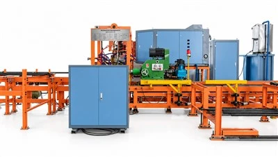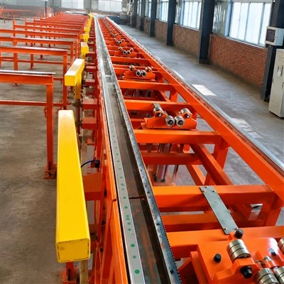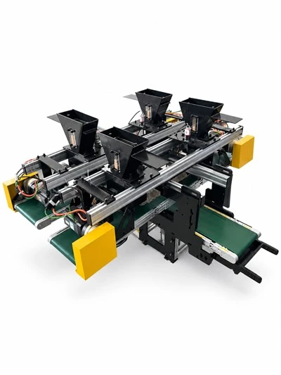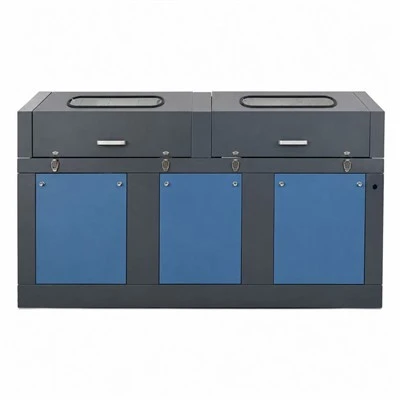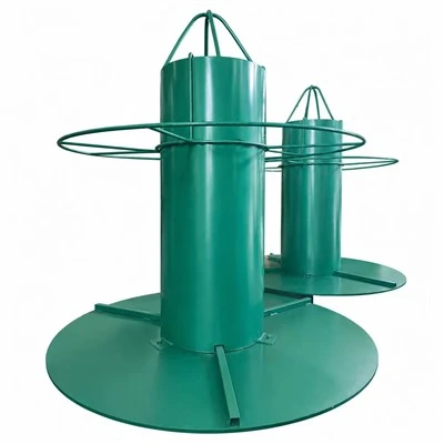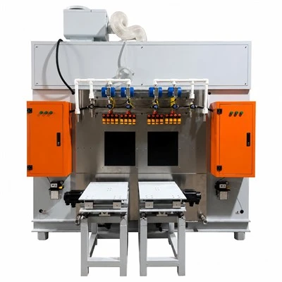

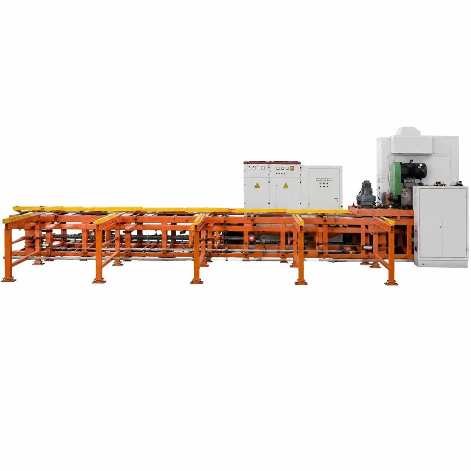


Baoding Sitai Induction Heating Equipment Manufacturing Co., Ltd. is one of the leading manufacturers and suppliers of spiral fin tube production line in China. We are committed to providing high quality customized products with competitive price. Welcome to contact us for quotation.
The Production Machine is the mechanical core section of the Spiral Fin Tube Production Line, designed for continuous manufacturing of spiral fin tubes through precise tube rotation, fin strip feeding, and spiral forming processes.
It integrates a rigid machine frame, drive system, tube rotation system, and strip feeding & spiral forming mechanism to ensure stable operation, accurate fin positioning, and high production efficiency.
As an essential part of the Spiral Fin Tube Machine, this unit provides reliable mechanical performance for producing high-quality spiral welded fin tubes widely used in heat exchangers, boilers, economizers, and industrial heat transfer equipment.
Main Components
Machine Frame & Drive System
The machine frame and drive system provide a stable foundation for the entire spiral fin tube manufacturing process.
The heavy-duty structure ensures excellent rigidity during continuous operation, while the drive system provides smooth and synchronized movement of the tube rotation and forming process.
Features:
- Strong and durable machine structure
- Stable transmission performance
- Reduced vibration during operation
- Designed for long-term continuous production
Tube Rotation System
The tube rotation system controls the rotation speed and positioning of the base tube during spiral fin welding production.
Through precise speed control and stable rotation, it ensures uniform fin pitch, accurate spiral angle, and consistent product quality.
Features:
- Stable tube rotation
- Adjustable production speed
- Accurate synchronization with fin feeding
- Suitable for different tube specifications
Strip Feeding & Spiral Forming System
The strip feeding and spiral forming system is responsible for delivering the fin strip and forming it into a continuous spiral shape around the base tube.
The system ensures smooth strip feeding, accurate positioning, and consistent spiral fin geometry during production.
Features:
- Precise fin strip feeding
- Stable spiral forming process
- Adjustable fin pitch
- Improved production consistency
Key Advantages
High Production Stability
The optimized mechanical structure ensures smooth operation and reliable performance for continuous spiral fin tube manufacturing.
Precise Fin Forming
The coordinated operation of tube rotation and strip feeding systems guarantees accurate spiral fin spacing and uniform product appearance.
Wide Manufacturing Capability
The production machine can support various spiral fin tube applications with different tube materials, fin materials, and production requirements.
Easy Operation and Maintenance
The practical mechanical design allows convenient adjustment, operation, and maintenance, reducing downtime during production.
Application
The Spiral Fin Tube Production Machine is widely used for manufacturing:
- Spiral fin tubes
- Heat exchanger tubes
- Boiler fin tubes
- Economizer tubes
-
Air cooler tubes
-
Industrial heat transfer components
Why Choose Our Spiral Fin Tube Production Machine?
Professional design for spiral fin tube manufacturing
01
Stable mechanical transmission system
02
Accurate tube rotation and fin forming performance
03
Suitable for continuous industrial production
04
Easy integration with complete fin-tube manufacturing lines
05
Product Keywords
- Spiral Fin Tube Machine
- Spiral Fin Tube Manufacturing Equipment
- Fin Tube Manufacturing Machine
- Spiral Welded Fin Tube Machine
- Fin Tube Making Machine
- Industrial Fin Tube Production Equipment
The Production Machine is the key mechanical section of the Spiral Fin Tube Production Line, providing precise forming performance and stable production capability for manufacturers of high-efficiency heat transfer tubes.
Frequently Asked Questions
Q: Why is stable tube rotation important before the fin strip reaches the welding point?
A: The tube rotation establishes the helical path. If rotation fluctuates or slips, the fin pitch and contact angle can change even when strip feed appears steady. Drive rollers, support points and clamping force should therefore be set so the tube rotates concentrically without surface damage. Motion stability is a mechanical prerequisite for repeatable welding rather than something that should be corrected later with more electrical power.
Q: How are tube rotation and axial movement synchronized for a new fin pitch?
A: The machine controller sets a relationship between rotational speed and axial travel based on the desired helix. After entering the nominal value, the actual tube should be measured because mechanical compliance and drive behavior can introduce a small difference. Fine adjustment is made from measured pitch over a meaningful tube length, then saved as a product-specific recipe.
Q: What effect does base-tube straightness have on the production machine?
A: A bent or strongly oval tube can move the weld point relative to the fin strip as it rotates. This changes contact pressure and may cause the fin to wander or the supports to load unevenly. Incoming tube quality should therefore be defined and checked. The production machine can guide and rotate the tube, but it should not be expected to straighten severe raw-material defects during fin winding.
Q: How should the strip feed be aligned with the rotating tube?
A: The strip should approach the contact point at the designed angle with its edge controlled by guides that do not twist the material. Check the path from the decoiler or accumulator through the final guide. A misalignment upstream can show up as variable fin angle or side load at the winding head, so adjusting only the last guide may not solve a persistent tracking problem.
Q: What causes vibration during high-speed spiral fin winding?
A: Potential sources include tube imbalance, worn support rollers, loose drive components, strip tension fluctuation or a resonance created by a long unsupported tube. Record where and at what speed the vibration appears, then inspect the mechanical system systematically. Reducing welding power will not correct a vibration whose origin is tube support or drive alignment.
Q: Can the mechanical production machine be integrated with an existing HF welder?
A: Integration is possible when the existing welding system has suitable capacity, output geometry and control interfaces. The project must define run-permit, speed reference, emergency-stop behavior and physical placement of the welding connection relative to the new winding head. Compatibility should be verified from drawings and electrical data before fabrication rather than assumed from rated kilowatts alone.
Q: What checks are useful after changing to a different tube length?
A: Confirm loading and discharge positions, support-roller spacing, axial travel limits and the stability of the tube at full extension. A longer tube can create greater deflection even when diameter and fin geometry are unchanged. Run a dry mechanical cycle before welding to make sure the tube remains supported throughout the full motion path and cannot contact guards or adjacent equipment.
Q: How does backlash in the carriage or axial drive affect a spiral fin tube?
A: Backlash can appear as a small pitch disturbance when travel direction changes, during startup or when the drive repeatedly corrects position. Inspect couplings, gearboxes, ball screws or rack-and-pinion components according to the machine design, and compare commanded motion with actual travel. Mechanical lost motion should be corrected at its source rather than hidden by modifying the nominal fin pitch.
Q: Why should long base tubes be supported at several points during rotation?
A: A long tube can sag between supports and may whip as rotational speed rises. This changes the contact point with the fin strip and can overload the drive or support rollers. Support spacing is selected from tube length, diameter, wall thickness and weight. As the winding head advances, the support plan must also avoid interference with the finished fins.
Q: What is the value of a dry mechanical cycle before enabling HF power?
A: A dry run verifies tube rotation, axial travel, strip path, limit positions and discharge motion without the additional risk of welding energy. It is especially useful after a size change or maintenance. If the mechanical helix is unstable with the power off, energizing the welder will only create a welded version of the same alignment problem and may damage material or tooling.
Q: What should be checked if the tube rotates but does not advance at the expected axial rate?
A: Compare commanded travel with the actual carriage or tube-feed movement and inspect for slip, drive overload, coupling wear or a mechanical obstruction. Because fin pitch depends on the ratio of rotation to axial travel, even a small loss of linear motion becomes a visible helix error. The axial drive should therefore be verified independently before correcting the pitch recipe.
Q: How can support rollers be set without marking the base tube?
A: Use enough contact to carry and stabilize the tube while keeping surface pressure within a range that will not indent or scratch the material. Roller profile and cleanliness should match the tube surface. On thin-wall products, a support that is too tight can create local ovality, so the tube should be rotated through a full cycle and checked for free movement before the winding operation starts.
Q: Why should strip-feed rollers be inspected for slip?
A: If strip speed is lower than the commanded value because of slip, the machine may still rotate the tube at the correct speed while the fin is stretched, tilted or spaced incorrectly. Check roller surface condition, clamping force and contamination when pitch or strip tension changes without a corresponding motion-command change. Mechanical feed accuracy is separate from the electronic recipe.
Q: What is the best way to confirm mechanical repeatability after a size change?
A: Return the machine to saved reference positions, run a dry cycle, then produce a short sample at reduced speed and measure pitch, fin angle and tube runout. If the same recipe needs a large new mechanical correction every changeover, inspect reference stops, clamps and adjustment scales. Repeatable mechanics reduce the amount of operator-dependent tuning required before welding begins.
Q: How should automatic tube loading be checked for different tube weights?
A: The loader must separate, lift and place each tube without dropping it onto the rotation supports or allowing two tubes to enter together. Heavier products change actuator load and stopping behavior, while small light tubes may roll differently on the rack. Cycle testing should include the minimum and maximum planned tube sizes, not only the easiest mid-range product.
Q: What should happen when a fin-strip joint approaches the winding head?
A: The production procedure should define whether the joint is allowed to pass through, requires reduced speed, or marks a section for rejection. Joint thickness and stiffness can disturb strip guidance or welding pressure. The accumulator and joining system may keep the line continuous, but quality rules still need to identify the tube length affected by the strip joint.
Hot Tags: spiral fin tube production line, China spiral fin tube production line manufacturers, suppliers, factory