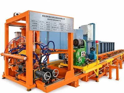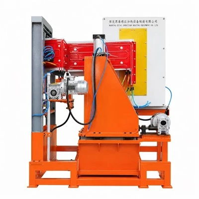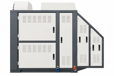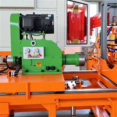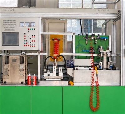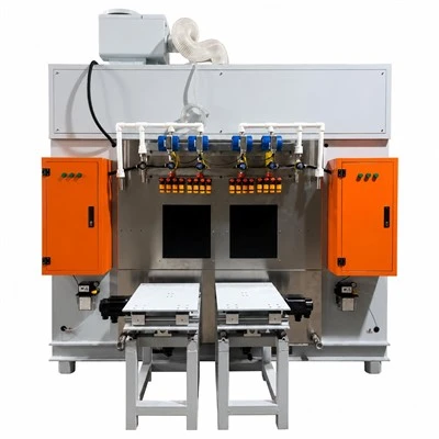

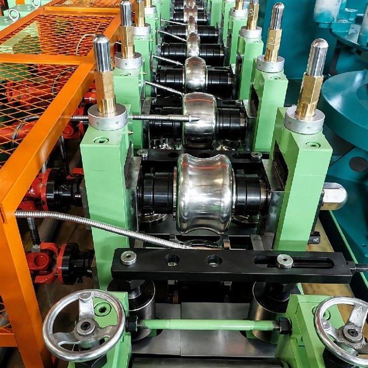
Baoding Sitai Induction Heating Equipment Manufacturing Co., Ltd. is one of the leading manufacturers and suppliers of copper and aluminum tube production line in China. We are committed to providing high quality customized products with competitive price. Welcome to contact us for quotation.
Line engineering for round and flat welded tube products
Copper and Aluminum Tube Production Line is engineered from the finished tube drawing backward: alloy, strip condition, tube section, wall thickness, welding method, target speed and downstream handling are reviewed before the forming passes and power system are fixed.
A typical line can include coil payoff, progressive forming, high-frequency welding, cooling, sizing, straightening and cutting or coiling. The exact modules depend on whether the product is a small round tube, a flat heat-exchanger tube or another confirmed section.
For projects that need both materials, the Copper and Aluminum Tube Production Line is reviewed as a shared mechanical platform only where the alloy range, tooling, welding process and changeover plan make that practical. Copper and aluminum are not treated as one identical welding recipe.
Two common line arrangements
Round tube line
Round-tube projects are defined by outside diameter, wall thickness, alloy and final tolerance. The pass schedule must bring the strip edges to the welding point without excessive twist or mismatch, then leave enough sizing capacity to meet the finished drawing.
Engineering points:
Progressive forming passes matched to strip thickness and alloy formability
Edge guidance through the welding zone and stable line-speed coordination
Sizing allowance based on the actual outside-diameter and roundness tolerance
Tooling sets confirmed for the specified diameter and wall-thickness range
Automation level selected from coil handling, cutoff and finished-product flow requirements
Flat tube line
Flat-tube production requires control of width, height, corner geometry and, where applicable, internal web or multi-channel features. The finished cross-section drawing is therefore needed before the roll sequence is designed.
Flat-tube design points
Roll geometry developed around the required width, height and corner profile
Dimensional checks focused on the features shown on the finished drawing
Guides and handling arranged to limit marking on surface-sensitive tube
Application review for heat-exchanger or thermal-management tube where the section is confirmed
Dedicated or shared tooling planned from the requested product mix and changeover frequency
Main process sections
The payoff section is selected from strip width and thickness, coil bore, maximum coil mass and the required line speed. Braking or powered payoff is chosen to suit strip handling and the amount of buffer available downstream.
Design checks:
Coil support and loading method sized for the confirmed maximum coil
Strip entry aligned with the first forming stand; tension hardware included only where specified
Coil-change method coordinated with any joining or accumulation equipment
Operator access and loading route confirmed from the customer layout
The forming section distributes deformation through several passes. Roll profiles are developed from the strip and finished section so the weld edges arrive at the joining point in a controlled position.
Forming checks
Pass sequence checked for gradual deformation rather than forcing shape change into the last stands
Guide pressure and roll finish selected with thin-wall and surface-sensitive material in mind
Reference settings provided for repeatable roll and guide adjustment
Separate tooling or change parts identified for each confirmed product family
At the welding section, high-frequency energy heats the approaching strip edges and the squeeze arrangement closes the seam. Power, frequency, output connection and edge condition are selected for the actual alloy and tube geometry.
Welding checks
Welding power matched to the qualified line-speed range
Seam quality verified by the inspection method specified for the product
Cooling and electrical loading documented for the selected power-supply model
Control interface coordinated with forming-line start, stop and speed signals
Sizing stands calibrate the welded section toward the final dimensions. The available correction is limited, so forming and welding alignment must already be stable before the product reaches this section.
Sizing checks
Roll adjustments referenced for repeatable size changeover
Outside diameter, height or width checked against the finished drawing
Enough sizing passes retained to correct normal process variation without overworking the tube
Thin-wall products reviewed for local flattening or surface marking during calibration
The straightening section corrects residual curvature within the capability of the selected arrangement. Severe incoming deformation or a systematic forming error should be corrected at its source rather than assigned to the straightener.
Straightening checks
Straightness target defined from the finished-product requirement
Roll pressure adjusted to avoid adding local marks or ovality
Inspection feedback used to separate straightening issues from upstream forming errors
Cutoff equipment is selected from tube section, wall thickness, target length, line speed and permitted burr or deformation. The method can differ between rigid straight lengths and products intended for coiling.
Cutoff checks
Length tolerance confirmed from the required cutoff process
Cutoff sequence synchronized with the line controller
Travel or timing range checked against the requested length range
Blade, saw or tooling access included in the maintenance plan
Finished-product handling is arranged to avoid scratching, uncontrolled drop or bending after cutoff. Conveyor length and collection method depend on tube length, surface requirement and the customer's packaging route.
Handling checks
Handling method selected from tube weight and package format
Contact materials reviewed for visible-surface requirements
Transfer signals coordinated with cutoff and collection equipment
Discharge orientation matched to the planned packing method
Information needed before line design
Product definition first
Provide alloy/temper, strip dimensions, finished section drawing, wall thickness and target speed. These inputs determine whether one mechanical platform is realistic for the planned product range.
Welding and inspection requirements
Define seam acceptance, dimensional tolerances, surface requirements and any online inspection. These requirements affect welding, cooling, sizing and cutoff design.
Changeover and factory interfaces
List the products that will share the line, expected changeover frequency, available floor space, electrical supply, compressed air and cooling-water conditions. Common equipment and material-specific tooling can then be separated clearly.
Copper Aluminum Aluminum alloy and different tube structures:
Round tubes
Flat tubes
Customized profiles
Project boundary
The quotation should state which modules are included, which existing customer equipment will remain, and the mechanical/electrical interface at every boundary. This avoids treating "complete line" as an undefined package.
Applications
Copper and aluminum tubes produced by SiTai production lines are widely used in:
- Heat Exchangers
- Air Conditioning Systems
- Refrigeration Equipment
- Automotive Radiators
-
Electric Vehicle Thermal Management Systems
-
Industrial Cooling Systems
-
Quotation inputs
For engineering review, send the finished tube drawing, alloy and temper, strip specification, target line speed, preferred cutoff or coiling method and any existing welding-power data. A layout drawing is especially useful when the line must fit an existing bay.
Frequently Asked Questions
Q: How is a round tube line different from a flat copper or aluminum tube line?
A: The forming sequence, roll geometry and dimensional control are different because a flat tube must maintain width, height and corner or web geometry rather than only roundness and outside diameter. Heat-exchanger flat tubes can also require tighter control of surface condition for later assembly. The correct line concept is selected from the finished cross-section drawing, not by converting a round-tube mill with a final flattening stand by default.
Q: Which process stages should be defined before designing the complete production line?
A: Clarify raw-material payoff, strip preparation, progressive forming, welding method, cooling, sizing, inspection, cutting or coiling and finished-product handling. For each stage, define who supplies the equipment and how signals are exchanged. A complete line performs best when these interfaces are engineered together, especially around welding speed, cooling distance and the transition from sizing to final handling.
Q: Can one production line manufacture both copper and aluminum tube?
A: A shared mechanical platform may be possible for an overlapping product range, but the welding process, tooling, lubrication, cleaning and parameter windows must be reviewed for each material. Copper and aluminum differ in thermal and mechanical behavior. If both are planned, the project should list the exact alloys, dimensions and changeover frequency so common equipment and material-specific components can be identified deliberately.
Q: What determines the number of forming and sizing stands?
A: The finished cross section, strip thickness, alloy formability, required dimensional accuracy and the amount of reduction that can be applied per pass all influence stand count. Too few passes can concentrate deformation and make the weld edges difficult to control; unnecessary stands add complexity. Pass design should distribute deformation smoothly while leaving enough sizing capacity to meet the final drawing.
Q: How should a line changeover between tube sizes be planned?
A: List which roll sets, guides, welding components and cutoff settings must change, then define reference positions or recipes for repeatability. Products with similar geometry may share some tooling, while larger changes need dedicated sets. A practical changeover plan also includes cleaning and inspection of the removed tools so the next setup does not start with damaged or contaminated components.
Q: What quality checks are useful on a copper or aluminum tube line?
A: Dimensional checks should cover the features on the product drawing, while weld quality, surface condition and straightness are evaluated at agreed intervals. For thin-wall products, local deformation from guides and cutoff equipment deserves attention. Inspection points should be positioned so a problem can be traced back to forming, welding or sizing rather than being discovered only after the finished tube has been packed.
Q: What factory information is needed before finalizing the line layout?
A: Provide available floor length and width, crane or forklift access, raw-material and finished-product flow, electrical supply, compressed air, cooling-water conditions and any column or pit constraints. The line should be arranged around material movement and maintenance access, not simply fitted into the longest empty aisle. Early layout confirmation reduces later changes to busbars, cooling pipes and handling equipment.
Hot Tags: copper and aluminum tube production line, China copper and aluminum tube production line manufacturers, suppliers, factory