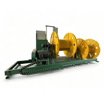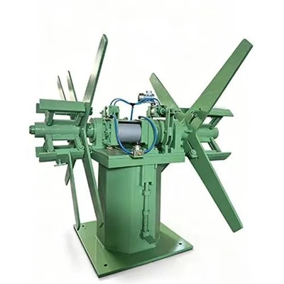

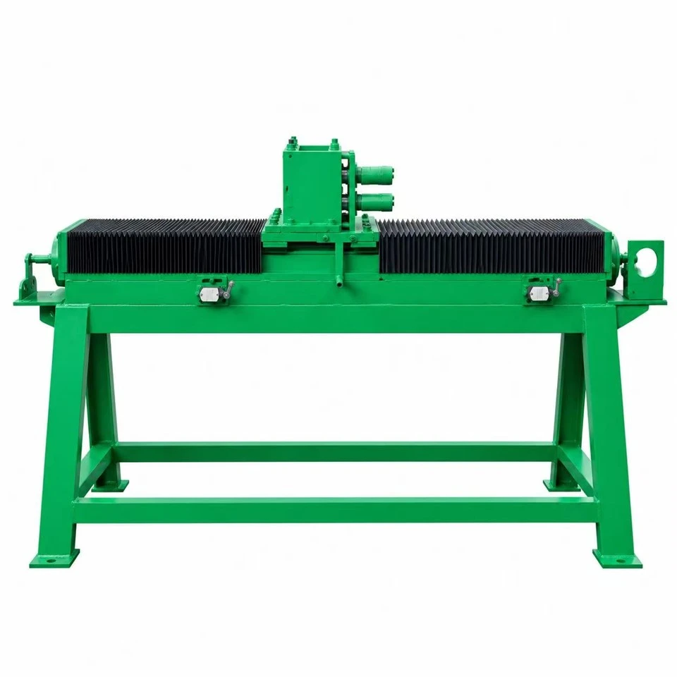
Baoding Sitai Induction Heating Equipment Manufacturing Co., Ltd. is one of the leading manufacturers and suppliers of traverse winding machine in China. We are committed to providing high quality customized products with competitive price. Welcome to contact us for quotation.
Traverse control for even coil build-up during continuous take-up
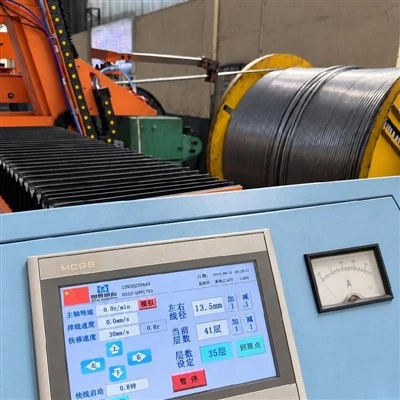
Traverse Winding Machine works beside the take-up machine and moves the guide laterally as the coil turns. Its job is to place each turn in a repeatable position so the package builds across the full coil width instead of forming ridges at the center or edges.
Traverse quality depends on the relationship between guide travel, take-up rotation, wire diameter and the changing package diameter. Those settings are commissioned on the actual coil geometry; a value that works on an empty mandrel may need correction as the coil builds.
What the operator adjusts
Traverse stroke and reversal
Left and right reversal points are set from the usable coil width, guide shape and wire diameter. Both ends are checked during a trial coil because overshoot or an incorrect limit can create edge build-up even when the middle layers look acceptable.
01
Pitch and guide speed
Guide speed is coordinated with winding speed so adjacent turns are placed with the required spacing. A change in wire diameter, package diameter or take-up speed can alter the correct relationship, so recipes are verified from the actual coil rather than copied blindly.
02
Guide alignment
The traverse axis should be parallel to the winding surface and the guide should approach the package without excessive side pull. Misalignment often shows up as a cone-shaped coil or repeated crossover at the same position.
03
Stop, restart and homing behavior
Controlled stops are checked as carefully as steady running. The guide should decelerate with the coiler, retain a known reference position and return to a verified home after maintenance before a saved recipe is used again.
04
Connection with the take-up machine
Encoder data, drive signals or a calculated motion relationship can be used to synchronize the two axes, depending on the machine design. The important requirement is that traverse motion follows the real winding process rather than operating as an independent fixed-speed reciprocation.
05
Applications
The Traverse Winding Machine is used where finished metallurgical wire is wound online and consistent layer placement is required. Typical applications include:
- Seamless cored wire production lines
- Welded cored wire production lines
- Metal powder filled wire manufacturing systems
- Automatic wire coiling and packaging equipment
Commissioning checks
- Verify usable traverse stroke with both empty and near-full coil diameters.
- Confirm left/right reversal points from the actual flange or package geometry.
- Run stop-and-restart tests so the guide does not lose its layer position.
- Check guide wear, axis alignment and homing reference during routine maintenance.
- Store separate settings when wire diameter or coil width changes materially.
Project matching
SiTai matches traverse stroke, guide arrangement and control interface to the take-up machine and finished coil drawing. The traversing unit is therefore specified as part of the winding process, not as an isolated motion axis.
For a proposal, provide wire diameter, coil inner and outer diameter, usable winding width, target coil weight, line-speed range and the take-up arrangement. Existing-machine centerline and control information are also useful on retrofit projects.
The final mechanical stroke, drive size, guarding and control functions are confirmed in the project specification.
Frequently Asked Questions
Q: How is traverse pitch selected for a cored wire coil?
A: Traverse pitch is related to wire diameter, the desired spacing between adjacent turns and the winding geometry. The objective is to place each turn predictably without forcing turns to ride over one another. Because the winding circumference changes as the coil builds, the control relationship should be tested over several layers instead of being judged only at the empty mandrel.
Q: Why are the traverse reversal points critical to coil quality?
A: If the guide reverses too early, the coil width is underused and material can build up in the center. If it travels too far, turns can fall against the flange or edge of the package and become trapped. The left and right reversal positions should be set from the actual coil geometry, with allowance for wire diameter and guide shape, and then observed as the package grows.
Q: What causes ridges or cone-shaped build-up on one side of the coil?
A: Common causes include unequal reversal positions, a traverse axis that is not parallel with the winding surface, inconsistent guide speed or a coiler centerline that is offset. Before changing software parameters, check the mechanical travel and guide alignment. A systematic cone usually indicates a geometric bias, while random crossovers can point to unstable wire tension or sudden speed changes.
Q: Should the traversing guide touch the wire tightly?
A: The guide should control lateral position without creating unnecessary friction or marking the surface. Groove shape and clearance are selected for the wire diameter and expected movement angle. Excessive confinement can add drag and transmit side load to the wire, whereas too much clearance can reduce placement accuracy. The guide condition should be inspected regularly because wear changes the effective path.
Q: How is the traverse synchronized with take-up rotation?
A: The controller relates lateral guide movement to the surface movement of the winding package. Depending on the design, this may use encoder information, drive data or a calculated recipe. The important point is that traverse motion represents the actual winding process, including changes as the coil grows. A fixed reciprocating speed that ignores take-up conditions is more likely to create crossovers.
Q: What should happen to the traverse during a controlled stop?
A: The guide should decelerate in coordination with the coiler so it does not continue sweeping sideways after the wire has nearly stopped. The restart sequence should also preserve the intended layer position instead of jumping to a new location. Site commissioning should include normal stop and restart tests because a system that coils well at steady speed can still create defects during transitions.
Q: Can one traversing system serve different coil widths?
A: Yes, when the available stroke and guide arrangement cover the requested package range. Each coil width needs its own reversal limits and may also need a different pitch or speed relationship. Recipe-controlled positions reduce manual setup, but physical end limits and clearances should still be checked whenever a substantially different coil format is introduced.
Q: How can operators diagnose repeated wire crossover at the same position?
A: Mark where the crossover occurs and compare it with the traverse position, coil diameter and direction of travel. A repeated defect near one edge suggests a reversal or alignment issue; a defect that occurs at a particular coil diameter can indicate an incorrect speed relationship as the package grows. This positional evidence is more useful than increasing tension in an attempt to force the wire into place.
Q: Why does guide inertia matter at traverse reversal?
A: The guide must stop and accelerate in the opposite direction at each edge of the coil. A heavy carriage or overly abrupt motion can overshoot the reversal point and place several turns too close to the flange. Acceleration and deceleration parameters should be tuned for the actual guide mass and production speed so the reversal is accurate without transmitting a sharp lateral pull into the wire.
Q: How should traverse recipes be managed when wire diameter changes slightly?
A: Even a modest diameter change can alter the ideal pitch between adjacent turns over many layers. Store a dedicated recipe when the difference is meaningful, or define a controlled adjustment rule based on measured coil build. Avoid compensating by moving only the end positions, because coil width and turn-to-turn spacing are separate parameters and affect different defects.
Q: What causes a traverse guide to hesitate in the middle of its stroke?
A: Possible causes include a drive fault, contaminated linear guide, damaged screw or belt, an incorrect motion profile or a cable carrier that is binding at one position. Because the defect is positional, first run the traverse without wire and observe current or load through the complete stroke. A mechanical tight spot should be corrected before changing the coil recipe.
Q: How should the wire guide be positioned relative to the winding surface?
A: The guide should place the wire onto the package at a controlled angle without excessive free span or rubbing. If it is too far away, the wire can wander before contact; if it is too close, changing coil diameter may create interference. The guide position should be checked at both the empty and near-full package diameters, not only at the start of winding.
Q: Why is independent traverse homing important after maintenance?
A: The controller's left and right limits are meaningful only if the carriage starts from a known mechanical reference. After a sensor, motor or drive component is serviced, re-home the axis and verify the physical zero before loading a production recipe. Otherwise, a numerically correct reversal position can be shifted across the coil and create repeated edge build-up.
Q: Can traverse motion be paused independently from winding?
A: Only if the control sequence has been designed for that operating mode. Stopping lateral motion while the coiler continues turning will stack wire in one narrow band and can quickly create a ridge. Maintenance or manual-jog functions should therefore use interlocks or clearly limited speeds so an operator cannot accidentally run normal take-up with the traverse disabled.
Q: What is the purpose of soft limits in addition to mechanical end stops?
A: Software limits prevent the carriage from reaching the physical end of travel during normal production, leaving the mechanical stop as a final protective boundary. Each coil recipe can use a smaller working window inside those limits. After maintenance or homing changes, verify both the machine travel and the saved recipe boundaries before running wire at production speed.
Hot Tags: traverse winding machine, China traverse winding machine manufacturers, suppliers, factory